When the machining accuracy of CNC machining center parts is poor, it should be analyzed and dealt with from the following three aspects.
(1)) The machining accuracy of the parts is poor, usually because the feed dynamics between the axes is not properly adjusted according to the error during the equipment adjustment, or because the transmission chain of each axis of the CNC machining center has changed after wear ( For example, clearance between screws during vertical processing, pitch error, axial movement, etc.). It can be handled by adjusting and correcting the gap offset from the start. When the dynamic tracking error is too large and an alarm is issued, it can be checked whether the speed of the servo motor is too high; whether the orientation detection element is protruding; whether the contact of the directional response cable connector is protruding; whether the corresponding analog output latch and gain potentiometer are protruding ; Whether the corresponding servo drive equipment is normal.
(2) The excessive adjustment of the movement of the CNC machining center leads to poor machining accuracy, which may be due to the short acceleration and deceleration time, which may appropriately prolong the speed change time; it is also possible that the connection between the servo motor and the lead screw is loose or the rigidity is too poor , and the gain of the azimuth loop can be appropriately reduced.

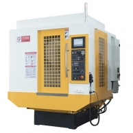
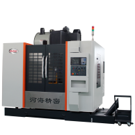
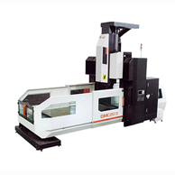
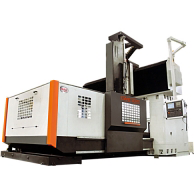
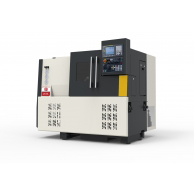
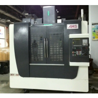
CNC machining center machine tool
( 3 ) The roundness of the biaxial connecting rod is out of the tolerance range
a. Axial deformation of a circle
This deformation may be caused by mechanical failure. The positioning accuracy of the axis is not good, or the clearance of the lead screw is not properly compensated, resulting in roundness errors when passing through the quadrant.
b. Oblique ellipse error (ellipse in 45 degree direction)
In this case, the bearing error value of each axis should be checked first. If the error is too large, the azimuth loop gain can be adjusted to sweep. Then check whether the interface board of the resolver or induction synchronizer is adjusted correctly, and then check whether the gap between the mechanical transmission pair is too large and whether the gap compensation is appropriate.